Introduction
Congo, or ACI 2.0 will support FCoE NPV on a single leaf. Seems to be only on new hardware such as the 93180YC-EX
Introduction
Prerequisites
Requirements
Configure
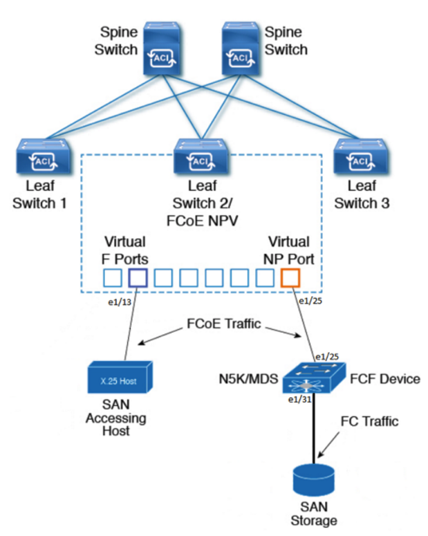
Network Diagram
Configurations
1 Tenant Configuration
Caveat: Need a native vlan-1 on all FCoE ports
Verify
Troubleshoot
Appendix
Native-Tenant Config
Scale Numbers (as of Congo 6/26 NPI)
N5K Configuration
Prerequisites
Requirements
- FCF – Fiber Channel Forwarder. Since ACI is NPV mode, some other storage switch needs to be able to apply zoning (storage world ACLs) this can be an MDS or a N5K with the right licensce
- Notice feature FCOE is enabled and feature NPIV is enabled.
- fcoe-npv converts the switch to an NPV switch, which is not what is needed for connection to ACI.
- ACI is the NPV switch, which needs to connect to an NPIV switch (FCF switch)
n5k-1# show feature
Feature Name          Instance  State
--------------------  --------  --------

fcoe                  1         enabled
fcoe-npv              1         disabled
fcsp                  1         disabled
fex                   1         disabled
fport-channel-trunk   1         disabled
interface-vlan        1         disabled
lacp                  1         enabled
ldap                  1         disabled
lldp                  1         enabled
msdp                  1         disabled
npiv                  1         enabled
npv                   1         disabled

n5k-1# show lic usage
Feature                      Ins  Lic   Status Expiry Date Comments
                                 Count
--------------------------------------------------------------------------------
FCOE_NPV_PKG                  Yes   -   Unused Never       -
FM_SERVER_PKG                 No    -   Unused             -
ENTERPRISE_PKG                Yes   -   Unused Never       -
FC_FEATURES_PKG               Yes   -   In use Never       -
VMFEX_FEATURE_PKG             No    -   Unused             -
ENHANCED_LAYER2_PKG           No    -   Unused             -
LAN_BASE_SERVICES_PKG         Yes   -   In use Never       -
LAN_ENTERPRISE_SERVICES_PKG   Yes   -   Unused Never       -
--------------------------------------------------------------------------------
n5k-1#
- A host with a CNA
- F ports connect to devices that are going to log in, F ports expect logins. Usually for hosts with a CNA that will be logging into to the Fiber Channel network
- NP ports are ports that do the logging in. A CNA on a host is an N port. NP stands for Node Proxy, that is, it itself performs a loging to the upstream NPIV switch. Since it is a proxy, it also forwards logs from actual N-ports.
- The FCF device connection to the ACI leaf NP port should be an F port. F ports expect logins.
Configure
Network Diagram
Configurations
There are some new access policies related to FCoE configuration on the ACI fabric. They are:
- Fiber Channel Domains – Like any other domain, ties to AAEPs. This Domain takes a VSAN pool, a VLAN pool, and a VSAN attribute.
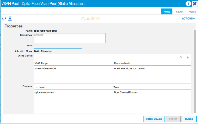
- VSAN Pool – Static pool for a range of VSANs. Ties to a Domain
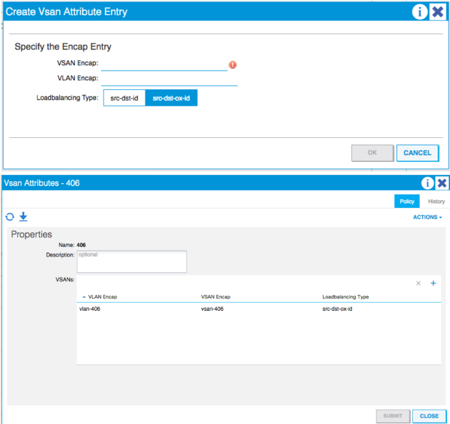
- VSAN Attributes – Takes a VLAN encap and ties it to a VSAN encap. Equivalent to NXOS command “vlan x, fcoe vsan x”, also has the option to change the LB option.
- Priority Flow Control Policy – IPG option to turn PFC to Auto|Off|On
- Slow Drain Policy – Specifies how to handle FCoE packets causing congestion
- Fiber Channel Interface Policy – Specifies the type of FC interface to be configured F|NP
- Fiber Channel SAN Policy – default policy for the FC Map MAC Address on the NPV leaf.
- Fiber Channel Node Policy – default policy for the loadbalance options
- QOS Class Policies – found under Global Policies. Used to set QoS and globally turn on PFC
We will now walk through the steps to configure the access policies for the topology above. One port needs to be configured for the FCF the other port for the host/CNA.
Starting from the bottom at Domains > Fiber Channel Domain:
- Right-Click and create a new Fiber Channel Domain
- Name
- Create a new VSAN Pool
- Name
- Encap Block
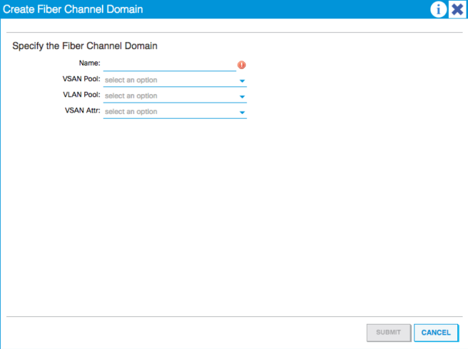
- Create a new VLAN Pool
- Needs to be static
- Create a new VSAN Attribute
- Name
- Click the + to add a new VSAN Attribute Entry
- Specify the VSAN Encap
- Specify the VLAN Encap
- Loadbalancing type (default is src-dst-ox-id).
- Under Global Policies > QoS Class Policies:
- Click Level1
- Enable PFC Admin State
- Set the CoS to 3
- Under Global Policies > AAEP:
- Create an AAEP for the Host/CNA
- Associate to the domain created
- Do not associate to interfaces just yet
- Create an AAEP for the FCF
- Associate to the domain created
- Do not associate to interfaces just yet.
- Create an AAEP for the Host/CNA
- Don’t do any EPG Deployment just yet
- Create Interface Policy Groups
- Create a Leaf Access IPG for the Host/CNA
- Create a Priority Flow Control policy and set to “ON”
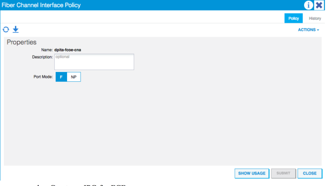
- Create a Fiber Channel Interface Policy
- Since this is the Host/CNA we need to configure the Leaf/ NPV switch virtual interface to be an “F” port since it is expecting a flogi from the host
- Create a Leaf Access IPG for the Host/CNA
- Associate the AAEP for the Host/CNA created in step 3a
- Create an IPG for FCF
- Use the PFC policy created in step 4ai above
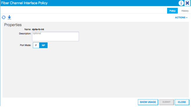
- Create a new Fiber Channel Interface Policy
- Since this is the external interface connecting to the FCF, the ACI Leaf/NPV switch needs to use an NP port in order to log in to the external NPIV F port.
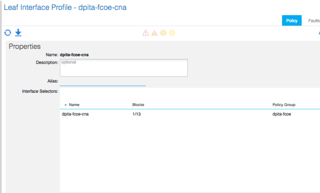
- Create an Interface Profile for the Host/CNA
- Associate the IPG created above
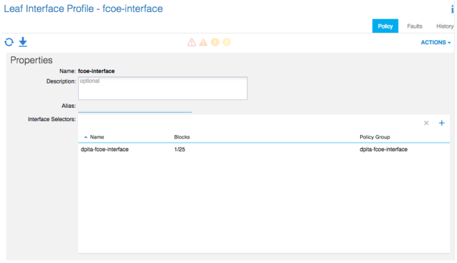
- Create an Interface Profile for the FCF
- Associate the IPG created above
- Create a Switch Profile for the Leaf that has the Host and FCF connected.
- Associate the interface selector profile for the host/CNA and the FCF
That should take care of access policies.
1 Tenant Configuration
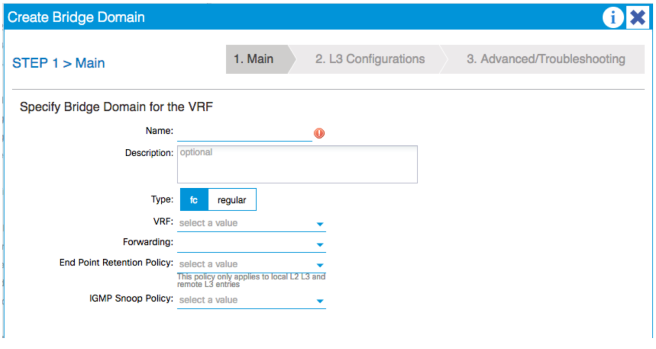
Moving on to the tenant configuration begin by creating a Bridge Domain:
- Make sure this bridge domain is set to “Type: FC”
- Name
- Type
- VRF
- Next, Next, Finish
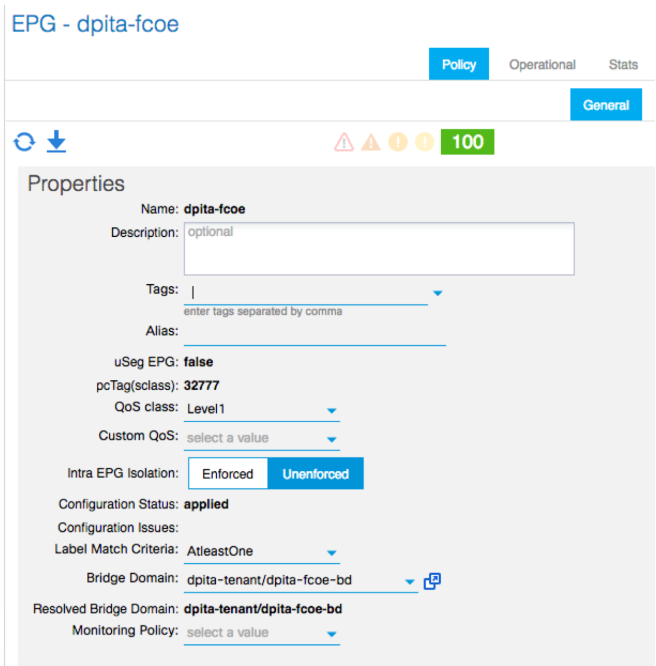
- Create an EPG
- Tie it to the FC-BD
- Set the QoS Class to the previously configured class with PFC enabled and CoS3
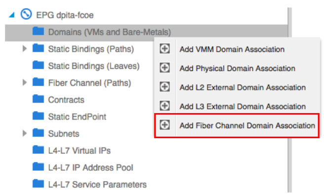
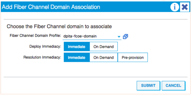
- Configure EPG
- Associate the fiber channel domain
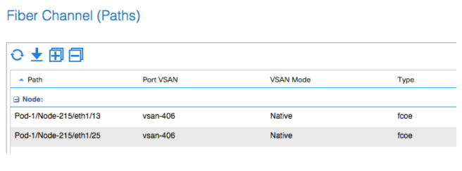
- Add a Fiber Channel Path
- Two paths are needed, one for the port with the Host/CNA and another for the FCF
- Right-click and select “deploy fiber channel”
- Specify the Path for the Host/CNA from the drop down.
- Enter the VSAN
- Select Native
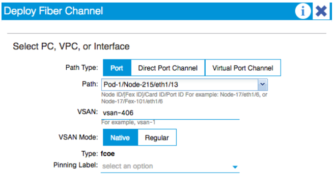
- Repeat for the other interface
Caveat: Need a native vlan-1 on all FCoE ports
At the time of writing. It is required that the port for the host/CNA have an access VLAN on it. This is required for FIP to take place. Without FIP the vfc toward the host will always be down, VSAN is initializing due to not all VSANs up on trunk, as seen in the verification output above.
To remedy this situation, there are two ways to proceed:
- Create a custom “native” tenant with a BD, VRF, EPG and a static path with vlan-1 as access
- In the same EPG, create a new BD and EPG with a static path of any vlan as access
Method 1:
Access policies need to be modified alittle for this method. A new Physical domain needs to be created as well as a VLAN pool for vlan-1. Finally associate that new domain to the AAEP for the host/CNA created in section 7.
From the APIC CLI/NXOS-style CLI copy and paste this configuration to configure a new tenant:
tenant native_tenant
vrf context nativeVrf
exit
bridge-domain nativebd
vrf member nativeVrf
exit
application nativeApp
epg nativeepg
bridge-domain member nativebd
set qos-class level1
exit
exit
interface bridge-domain nativebd
Should look like the below:
fab2-p1-apic1# config t
fab2-p1-apic1(config)# tenant native_tenant
fab2-p1-apic1(config-tenant)# vrf context nativeVrf
fab2-p1-apic1(config-tenant-vrf)# exit
fab2-p1-apic1(config-tenant)# bridge-domain nativebd
fab2-p1-apic1(config-tenant-bd)# vrf member nativeVrf
fab2-p1-apic1(config-tenant-bd)# exit
fab2-p1-apic1(config-tenant)# application nativeApp
fab2-p1-apic1(config-tenant-app)# epg nativeepg
fab2-p1-apic1(config-tenant-app-epg)# bridge-domain member nativebd
fab2-p1-apic1(config-tenant-app-epg)# set qos-class level1
fab2-p1-apic1(config-tenant-app-epg)# exit
fab2-p1-apic1(config-tenant-app)# exit
fab2-p1-apic1(config-tenant)# interface bridge-domain nativebd
fab2-p1-apic1(config-tenant-interface)# exit
fab2-p1-apic1(config-tenant)# exit
fab2-p1-apic1(config)#
fab2-p1-apic1(config)#
Now, navigate in the GUI to the newly created “native_tenant” > nativeApp > nativeepg Deploy a static path to the interface with the host, for vlan-1 as access/untagged. Associate the domain created above. Another option is to use a static leaf binding to deploy this native vlan on all interfaces of the leaf.
At this point the vfc should be up and FIP should have worked
Verification:
fab2-p1-leaf5-EX# show int e1/13 sw
Name: Ethernet1/13
  Switchport: Enabled
  Switchport Monitor: not-a-span-dest
  Operational Mode: trunk
  Access Mode Vlan: 7 (default)
  Trunking Native Mode VLAN: 7 (default)
  Trunking VLANs Allowed: 2,7,17-18
  FabricPath Topology List Allowed: 0
  Administrative private-vlan primary host-association: none
  Administrative private-vlan secondary host-association: none
  Administrative private-vlan primary mapping: none
  Administrative private-vlan secondary mapping: none
  Administrative private-vlan trunk native VLAN: none
  Administrative private-vlan trunk encapsulation: dot1q
  Administrative private-vlan trunk normal VLANs: none
  Administrative private-vlan trunk private VLANs: none
  Operational private-vlan: none
fab2-p1-leaf5-EX# show vlan ex

 VLAN Name                             Status    Ports
 ---- -------------------------------- --------- -------------------------------
 1    dpita-tenant:dpita-AP:dpita-EPG4 active    Eth1/42
 2    native_tenant:nativebd           active    Eth1/13
 7    native_tenant:nativeApp:nativeep active    Eth1/13
      g
 17   dpita-tenant:dpita-fcoe-bd       active    Eth1/13, Eth1/25
 18   dpita-tenant:dpita-AP:dpita-fcoe active    Eth1/13, Eth1/25
 21   mgmt:inb                         active    --
 24   dpita-tenant:dpita-BD2           active    Eth1/42
 25   dpita-tenant:dpita-AP:dpita-EPG2 active    Eth1/42
 26   dpita-tenant:dpita-BD1           active    Eth1/42
 27   dpita-tenant:dpita-AP:dpita-EPG1 active    Eth1/42
 28   dpita-tenant:dpita-BD3           active    Eth1/42
 29   dpita-tenant:dpita-AP:dpita-EPG3 active    Eth1/42
 30   dpita-tenant:dpita-BD4           active    Eth1/42

 VLAN Type  Vlan-mode  Encap
 ---- ----- ---------- -------------------------------
 1    enet  CE         vlan-391
 2    enet  CE         vxlan-16154555
 7    enet  CE         vlan-1
 17   enet  CE         vxlan-16547725
 18   enet  CE         vlan-406
 21   enet  CE         vxlan-15728622
 24   enet  CE         vxlan-16089028
 25   enet  CE         vlan-356
 26   enet  CE         vxlan-16646016
 27   enet  CE         vlan-390
 28   enet  CE         vxlan-16416667
 29   enet  CE         vlan-373
 30   enet  CE         vxlan-16252848
fab2-p1-leaf5-EX#


fab2-p1-leaf5-EX# show int vfc 1/13
Vfc1/13 is trunking
    Bound interface is Ethernet1/13
    Hardware is Ethernet
    Port WWN is 20:0D:E0:0E:DA:A2:F2:CB
    Admin port mode is F, trunk mode is on
    Port mode is TF
    Port vsan is 406
    Speed is auto
    Trunk vsans (admin allowed and active) (406)
    Trunk vsans (up)                       (406)
    Trunk vsans (isolated)                 ()
    Trunk vsans (initializing)             ()
    205 fcoe in packets
    81592 fcoe in octets
    861 fcoe out packets
    1283264 fcoe out octets
Method 2:
This method still requires some modification of the access policies but will allow an access/untagged VLAN to be deployed as well as allow the server data traffic to be inside the user Tenant, assuming the server is sending untagged traffic.
Under the access policies, use an existing VLAN pool and tie it to a physical domain. Tie this physical domain once again to the AAEP for the host/CNA.
Under the user tenant, create a new BD of type regular, create an SVI if desired. Create a new EPG, associate the physical domain and the new static path as access/untagged.
At this point the vfc should be up and FIP should have worked
Verification:
fab2-p1-leaf5-EX# show int e1/13 sw
Name: Ethernet1/13
  Switchport: Enabled
  Switchport Monitor: not-a-span-dest
  Operational Mode: trunk
  Access Mode Vlan: 1 (default)
  Trunking Native Mode VLAN: 1 (default)
  Trunking VLANs Allowed: 1,17-18,30
  FabricPath Topology List Allowed: 0
  Administrative private-vlan primary host-association: none
  Administrative private-vlan secondary host-association: none
  Administrative private-vlan primary mapping: none
  Administrative private-vlan secondary mapping: none
  Administrative private-vlan trunk native VLAN: none
  Administrative private-vlan trunk encapsulation: dot1q
  Administrative private-vlan trunk normal VLANs: none
  Administrative private-vlan trunk private VLANs: none
  Operational private-vlan: none
fab2-p1-leaf5-EX# show vlan ex

 VLAN Name                             Status    Ports
 ---- -------------------------------- --------- -------------------------------
 1    dpita-tenant:dpita-AP:dpita-     active    Eth1/13
      fcoe-data
 17   dpita-tenant:dpita-fcoe-bd       active    Eth1/13, Eth1/25
 18   dpita-tenant:dpita-AP:dpita-fcoe active    Eth1/13, Eth1/25
 21   mgmt:inb                         active    --
 22   dpita-tenant:dpita-BD4           active    Eth1/42
 23   dpita-tenant:dpita-AP:dpita-EPG4 active    Eth1/42
 24   dpita-tenant:dpita-BD1           active    Eth1/42
 25   dpita-tenant:dpita-AP:dpita-EPG1 active    Eth1/42
 26   dpita-tenant:dpita-BD3           active    Eth1/42
 27   dpita-tenant:dpita-AP:dpita-EPG3 active    Eth1/42
 28   dpita-tenant:dpita-BD2           active    Eth1/42
 29   dpita-tenant:dpita-AP:dpita-EPG2 active    Eth1/42
 30   dpita-tenant:dpita-fcoe-data-bd  active    Eth1/13

 VLAN Type  Vlan-mode  Encap
 ---- ----- ---------- -------------------------------
 1    enet  CE         vlan-405
 17   enet  CE         vxlan-16547725
 18   enet  CE         vlan-406
 21   enet  CE         vxlan-15728622
 22   enet  CE         vxlan-16252848
 23   enet  CE         vlan-391
 24   enet  CE         vxlan-16646016
 25   enet  CE         vlan-390
 26   enet  CE         vxlan-16416667
 27   enet  CE         vlan-373
 28   enet  CE         vxlan-16089028
 29   enet  CE         vlan-356
 30   enet  CE         vxlan-16678779
fab2-p1-leaf5-EX#
fab2-p1-leaf5-EX# show int vfc 1/13
Vfc1/13 is trunking
    Bound interface is Ethernet1/13
    Hardware is Ethernet
    Port WWN is 20:0D:E0:0E:DA:A2:F2:CB
    Admin port mode is F, trunk mode is on
    Port mode is TF
    Port vsan is 406
    Speed is auto
    Trunk vsans (admin allowed and active) (406)
    Trunk vsans (up)                       (406)
    Trunk vsans (isolated)                 ()
    Trunk vsans (initializing)             ()
    205 fcoe in packets
    81592 fcoe in octets
    861 fcoe out packets
    1283264 fcoe out octets
Verify
fab2-p1-leaf5-EX# show vsan membership
vsan 406 interfaces
    vfc1/13            vfc1/25
fab2-p1-leaf5-EX# show int vfc1/25
Vfc1/25 is trunking
    Bound interface is Ethernet1/25
    Hardware is Ethernet
    Port WWN is 20:19:E0:0E:DA:A2:F2:CB
    Admin port mode is NP, trunk mode is on
    Port mode is TNP
    Port vsan is 406
    Speed is auto
    Trunk vsans (admin allowed and active) (406)
    Trunk vsans (up)                       (406)
    Trunk vsans (isolated)                 ()
    Trunk vsans (initializing)             ()
    6 fcoe in packets
    804 fcoe in octets
    0 fcoe out packets
    0 fcoe out octets
    Interface last changed at 2016-06-03T16:55:17.330+03:00
fab2-p1-leaf5-EX#

fab2-p1-leaf5-EX# show npv status

npiv is enabled

disruptive load balancing is disabled

External Interfaces:
====================
  Interface: vfc1/25, State: up
        VSAN:  406, State: up , FCID: E8:00:20

  Number of External Interfaces: 1

Server Interfaces:
==================
  Interface: vfc1/13, VSAN:  406, State: wait-flogi

  Number of Server Interfaces: 1
========================
fab2-p1-leaf5-EX#
fab2-p1-leaf5-EX#
fab2-p1-leaf5-EX#
fab2-p1-leaf5-EX# show fcoe database
-------------------------------------------------------------------------------
INTERFACE       FCID            PORT NAME               MAC ADDRESS
-------------------------------------------------------------------------------
vfc1/25         E8:00:20        20:7C:8C:60:4F:3A:32:BF 8C:60:4F:3A:32:A0

Total number of flogi count from FCoE devices = 1.
fab2-p1-leaf5-EX# show vlan ex

 VLAN Name                             Status    Ports
 ---- -------------------------------- --------- -------------------------------
 10   dpita-tenant:dpita-fcoe-bd       active    Eth1/13, Eth1/25
 11   dpita-tenant:dpita-didata-       active    Eth1/13, Eth1/25
      recreate:epg2
 18   mgmt:inb                         active    --
 20   dpita-tenant:dpita-BD3           active    Eth1/42
 21   dpita-tenant:dpita-AP:dpita-EPG3 active    Eth1/42
 22   dpita-tenant:dpita-BD4           active    Eth1/42
 23   dpita-tenant:dpita-AP:dpita-EPG4 active    Eth1/42
 24   dpita-tenant:dpita-BD1           active    Eth1/42
 25   dpita-tenant:dpita-AP:dpita-EPG1 active    Eth1/42
 26   dpita-tenant:dpita-BD2           active    Eth1/42
 28   dpita-tenant:dpita-AP:dpita-EPG2 active    Eth1/42

 VLAN Type  Vlan-mode  Encap
 ---- ----- ---------- -------------------------------
 10   enet  CE         vxlan-16547725
 11   enet  CE         vlan-406
 18   enet  CE         vxlan-15728622
 20   enet  CE         vxlan-16416667
 21   enet  CE         vlan-373
 22   enet  CE         vxlan-16252848
 23   enet  CE         vlan-391
 24   enet  CE         vxlan-16646016
 25   enet  CE         vlan-390
 26   enet  CE         vxlan-16089028
 28   enet  CE         vlan-356
Troubleshoot
Helpful commands:
- show vlan ex
- Will show the VLAN and VSANs deployed on a switch
- show int e1/x switchport
- Will show the VLANs/VSANs deployed on an interface
- show fcoe database
- NP port logins
- show npv status
- Displays information on NPV and the Externa/Server facing interfaces and VSANs
- show int vfc
- Displays information on the particular virtual fiber channel interface. Status, Binding, VSAN, and port mode
- show vsan membership
- Displays all VSANs and the VFCs that are members of each VSAN
- show vlan fcoe
- Displays binding of VLAN to BD to VSAN and its current state
- show lldp interface e1/x
- Shows DCBX information
- show npv flogi-table
- Shows logins from Server CNAs on the VFC F-port
FIP:
- Uses ethertype 0x8914. Goes directly to the CPU
- FCoE switches uses ethertype 0x8906
to troubleshoot FIP use the following command:
tcpdump -xxi tahoe0 > /tmp/inband.log
tcpdump -i kpm_inb | grep 8914
15:08:06.915374 0e:fc:00:e8:00:40 (oui Unknown) > 8c:60:4f:3a:32:b8 (oui Unknown), ethertype Unknown (0x8914), length 56:
15:08:06.928086 00:22:bd:d6:57:e5 (oui Unknown) > 01:10:18:01:00:02 (oui Unknown), ethertype Unknown (0x8914), length 56:
15:08:06.949260 00:22:bd:d6:57:e5 (oui Unknown) > 01:10:18:01:00:02 (oui Unknown), ethertype Unknown (0x8914), length 56:
15:08:06.961130 00:22:bd:d6:57:e5 (oui Unknown) > 01:10:18:01:00:02 (oui Unknown), ethertype Unknown (0x8914), length 56:
15:08:06.961990 00:22:bd:d6:57:e5 (oui Unknown) > 01:10:18:01:00:02 (oui Unknown), ethertype Unknown (0x8914), length 56:
15:08:06.962840 8c:60:4f:3a:32:b8 (oui Unknown) > 00:22:bd:d6:57:e5 (oui Unknown), ethertype Unknown (0x8914), length 2172:
FCoE internal commands (From NPI slides):
Run these commands from vsh
FC PM internal commands
- sh port internal event-history msg
- sh port internal event-history interface vfcx/y
- sh port internal event-history errors
VSAN Manager Internal commands
- Show vsan internal event-history errors
- Show vsan internal event-history msgs
FcFwd Commands
- sh system internal fcfwd bdportmap entries (bd-fd-encap vlan table)
- sh system internal fcfwd mpmap vfcs
- sh system internal fcfwd pcmap (eth shadow PC)
FCoE and VFC show internal commands
- show system internal fcoe_mgr event-history errors
- show system internal fcoe_mgr event-history msgs
- show system internal fcoe_mgr info global
- show system internal fcoe_mgr mem-stats detail
- show system internal fcoe_mgr event-history interface vfc <vfc-id>
- show system internal fcfwd mpmap vfcs
NPV Internal commands
- show npv internal event-history distrib-fsm
- show npv internal event-history ext-if-fsm interface <if> vsan <vsan>
- show npv internal event-history ext-if-fsm interface <if>
- show npv internal event-history ext-if-fsm vsan <vsan>
- show npv internal event-history ext-if-fsm
- show npv internal event-history flogi-fsm interface <if>
- show npv internal event-history flogi-fsm pwwn <wwn>
- show npv internal event-history flogi-fsm vsan <vsan>
- show npv internal event-history flogi-fsm
- show npv internal event-history svr-if-fsm interface <if>
- show npv internal event-history svr-if-fsm vsan <vsan>
- show npv internal event-history svr-if-fsm
- show npv internal event-history errors
- show npv internal event-history events
- show npv internal event-history msgs
FCoE Logs:
- /tmp/logs/fcoe_mgr_trace.txt
- /tmp/logs/fcnportmux_debug_xx
- /tmp/logs/port_mgr.log
Appendix
Native-Tenant Config
The following configuration can be copy/pasted into the APIC NXOS-CLI. The next step would to add static paths for the interfaces connected to CNAs.
config t
tenant native_tenant
vrf context nativeVrf
exit
bridge-domain nativebd
vrf member nativeVrf
exit
application nativeApp
epg nativeepg
bridge-domain member nativebd
set qos-class level1
exit
exit
interface bridge-domain nativebd
exit
exit
Scale Numbers
- Total VSAN per Leaf: 32
- Total VFC per Leaf: 48
- Total FDISC per port: 255
- Total FDISC per SB Leaf: 512
N5K Configuration
!Command: show running-config
!Time: Fri Jun 18 10:49:26 2010
version 5.2(1)N1(6)
feature fcoe
hostname n5k-1
feature npiv
feature telnet
cfs ipv4 distribute
feature lldp
banner motd #Nexus 5000 Switch
#
ip domain-lookup
system qos
service-policy type queuing input fcoe-default-in-policy
service-policy type queuing output fcoe-default-out-policy
service-policy type qos input fcoe-default-in-policy
service-policy type network-qos fcoe-default-nq-policy
snmp-server user admin network-admin auth md5 0xc4ff8bf3d16d4eeac2958943bd7b36e7
localizedkey
vrf context management
ip route 0.0.0.0/0 172.18.217.1
vlan 1
vlan 406
fcoe vsan 406
port-profile default max-ports 512
vsan database
vsan 406
device-alias mode enhanced
device-alias database
device-alias name c210-h4-a pwwn 20:00:00:22:bd:d6:57:e5
device-alias name c210-h4-b pwwn 20:00:00:22:bd:d6:57:e6
device-alias name fas3040-a pwwn 50:0a:09:81:87:59:70:17
device-alias name fas3040-b pwwn 50:0a:09:82:87:59:70:17
device-alias commit
fcdomain fcid database
vsan 406 wwn 50:0a:09:81:87:59:70:17 fcid 0xe80000 dynamic
! [fas3040-a]
vsan 406 wwn 20:19:e0:0e:da:a2:f2:cb fcid 0xe80020 dynamic
vsan 406 wwn 20:00:00:22:bd:d6:57:e5 fcid 0xe80040 dynamic
! [c210-h4-a]
interface vfc125
bind interface Ethernet1/25
switchport trunk allowed vsan 406
no shutdown
interface vfc131
bind interface Ethernet1/31
switchport trunk allowed vsan 406
no shutdown
vsan database
vsan 406 interface vfc125
vsan 406 interface vfc131
interface Ethernet1/25
switchport mode trunk
switchport trunk allowed vlan 406
interface Ethernet1/26
interface Ethernet1/27
interface Ethernet1/28
interface Ethernet1/29
interface Ethernet1/30
interface Ethernet1/31
switchport mode trunk
switchport trunk allowed vlan 406
line console
line vty
boot kickstart bootflash:/n5000-uk9-kickstart.5.2.1.N1.6.bin
boot system bootflash:/n5000-uk9.5.2.1.N1.6.bin
zone mode enhanced vsan 406
!Active Zone Database Section for vsan 406
zone name h4-netapp vsan 406
member device-alias c210-h4-a
member device-alias c210-h4-b
member device-alias fas3040-a
member device-alias fas3040-b
zoneset name vsan406-dpita vsan 406
member h4-netapp
zoneset activate name vsan406-dpita vsan 406
do clear zone database vsan 406
!Full Zone Database Section for vsan 406
zone name h4-netapp vsan 406
member device-alias c210-h4-a
member device-alias c210-h4-b
member device-alias fas3040-a
member device-alias fas3040-b
zoneset name vsan406-dpita vsan 406
member h4-netapp
zone commit vsan 406
