Cisco Live 2016 – Las Vegas

Hello Everyone,

Once again, I apologize for the lack of activity. If you have not guessed based on the title, my excuse this time is that i have been working quite hard on my session for this years Cisco Live at the Mandalay Bay in Las Vegas, Nevada!!

Here is a link to my session and abstract!

CL-2016 Catalog

I’ll give you all a preview. The title is “A Technical Introduction into ACI” where I hope to go over some basics from a TAC perspective. Very high level, what you can, how it works, some important tidbits and things to keep in mind.

I really look forward to presenting. This is a new session and a completely different approach from last years session “Understanding, Verifying, and Troubleshooting ACI Configuration Policies” which was between intermediate and advanced. This year its a beginner session!

Also been working on some cool new features coming out later this year!

Stay Tuned!

Intermittent Traffic due to TCN

Introduction

When troubleshooting, if there is intermittent traffic loss it could be for a number of reasons. This article will cover one possible reason. The case where TCNs will cause ACI to flush endpoints and re-learn immediately.


Intermittent Traffic loss due to TCN

Screen Shot 2016-04-13 at 7.47.27 AM.png

Symptoms:

  • Intermittent packet loss
  • ACI leaf shows endpoint changing NS ADJ
module-1# show system internal epmc endpoint mac 001e.795e.9000 | grep -B 3 -A 18 802.1Q/306 

MAC : 001e.795e.9000 ::: Num IPs : 0
Vlan id : 38 ::: Vlan vnid : 9488 ::: BD vnid : 15630220
Encap vlan : 802.1Q/306       
VRF name : PROD:Hybrid  ::: VRF vnid : 2981888
phy if : 0x16000001 ::: tunnel if : 0 ::: Interface : port-channel2
Flags : 0x80004805
Ref count : 4 ::: sclass : 32773
Timestamp : 02/19/1970 09:30:05.107000
last mv timestamp 01/01/1970 05:30:00.000000 ::: ep move count : 0
last loop_detection_ts 01/01/1970 05:30:00.000000
previous if : 0 ::: loop detection count : 0
EP Flags : local,vPC,MAC,sclass,timer,
Aging:Timer-type : Host-tracker timeout ::: Timeout-left : 900 ::: Hit-bit : No ::: Timer-reset count : 0

PD handles: 
Bcm l2 hit-bit : No
[L2]: Asic : NS ::: ADJ : 0x32 ::: LST SA : 0x618 ::: LST DA : 0x618 ::: GST ING : 0x1b6c ::: BCM : Yes
<detail> SDB Data:
        is_ns_learn_port_valid : YES ::: ns_learn_port 6
        is_bcm_trunk_id_valid : YES ::: bcm_trunk_id 0x2(2)
::::
module-1# 
module-1# 
module-1# show system internal epmc endpoint mac 001e.795e.9000 | grep -B 3 -A 18 802.1Q/306 

MAC : 001e.795e.9000 ::: Num IPs : 0
Vlan id : 38 ::: Vlan vnid : 9488 ::: BD vnid : 15630220
Encap vlan : 802.1Q/306       
VRF name : PROD:Hybrid  ::: VRF vnid : 2981888
phy if : 0x16000001 ::: tunnel if : 0 ::: Interface : port-channel2
Flags : 0x80004805
Ref count : 4 ::: sclass : 32773
Timestamp : 02/19/1970 09:30:10.077000
last mv timestamp 01/01/1970 05:30:00.000000 ::: ep move count : 0
last loop_detection_ts 01/01/1970 05:30:00.000000
previous if : 0 ::: loop detection count : 0
EP Flags : local,vPC,MAC,sclass,timer,
Aging:Timer-type : Host-tracker timeout ::: Timeout-left : 899 ::: Hit-bit : Yes ::: Timer-reset count : 0

PD handles: 
Bcm l2 hit-bit : Yes
[L2]: Asic : NS ::: ADJ : 0x28 ::: LST SA : 0x618 ::: LST DA : 0x618 ::: GST ING : 0x1b6c ::: BCM : Yes
<detail> SDB Data:
        is_ns_learn_port_valid : YES ::: ns_learn_port 6
        is_bcm_trunk_id_valid : YES ::: bcm_trunk_id 0x2(2)
::::

Since the ADJ always points to the same encap and forwarding does work, its an indication that ACI is just reacting. At this point checking EPMC for why the flapping showed alot of churn for the particular MAC. The below is just an excerpt of EPMC log showing some add or delete. This was in the logs over and over for add/delete/and update.


EPM EP req :: EP_OP=ADD VLAN 38 MAC:=001e.795e.9000 #IPs=0
[2016 Apr  7 22:00:34.743712073:3137103690:epmc_pd_ns_prog_l2_entry:2279:t] BD-vnid: 15630220 MAC: 001e.795e.9000 smod: 0 sport: 6 sclass: 32773
[2016 Apr  7 22:00:34.743722137:3137103697:epmc_pd_bcm_l2_addr_add:283:t] mac= 001e.795e.9000 vid = 38 port 0x0 tid = 2 for bcm_l2_addr_add
[2016 Apr  7 22:00:34.743724803:3137103698:epmc_ep_age_add:407:t] adding timer for Host-tracker timeout for 900 secs for EP 0x9c77d06      EPM EP key :: BD 15630220 MAC:=001e.795e.9000
EPM EP entry :: VLAN 38 MAC:=001e.795e.9000 #IPs=0
EPM EP req :: EP_OP=UPD VLAN 38 MAC:=001e.795e.9000 #IPs=1
EPM EP req :: EP_OP=UPD VLAN 38 MAC:=001e.795e.9000 #IPs=0
EPM EP req :: EP_OP=UPD VLAN 38 MAC:=001e.795e.9000 #IPs=1
EPM EP req :: EP_OP=UPD VLAN 38 MAC:=001e.795e.9000 #IPs=0
EPM EP req :: EP_OP=UPD VLAN 38 MAC:=001e.795e.9000 #IPs=1
EPM EP req :: EP_OP=UPD VLAN 38 MAC:=001e.795e.9000 #IPs=0
EPM EP req :: EP_OP=UPD VLAN 38 MAC:=001e.795e.9000 #IPs=1
EPM EP req :: EP_OP=UPD VLAN 38 MAC:=001e.795e.9000 #IPs=0
EPM EP req :: EP_OP=UPD VLAN 38 MAC:=001e.795e.9000 #IPs=1
EPM EP req :: EP_OP=UPD VLAN 38 MAC:=001e.795e.9000 #IPs=0

Finally, checking MCP will have our answer.


Leaf1# show mcp internal inf vlan 306 
Warning: could not get list of reserved vlans
-------------------------------------------------
               PI VLAN: 38 Up
            Encap VLAN: 306
       PVRSTP TC Count: 116180
         RSTP TC Count: 116019
Last TC flush at Thu Apr  7 23:36:22 2016
 on Tunnel5

Following all the TCNs from leaf to leaf and then external the fabric on the traditional switches using the

SW1#show spanning-tree vlan 831 detail 

 VLAN0831 is executing the ieee compatible Spanning Tree protocol
  Bridge Identifier has priority 32768, sysid 831, address 001d.a2e3.f000
  Configured hello time 2, max age 20, forward delay 15
  Current root has priority 33599, address 001a.e29f.bc00
  Root port is 47 (GigabitEthernet0/47), cost of root path is 19
  Topology change flag not set, detected flag not set
  Number of topology changes 1767 last change occurred 1w1d ago
          from GigabitEthernet0/7
  Times:  hold 1, topology change 35, notification 2
          hello 2, max age 20, forward delay 15 
  Timers: hello 0, topology change 0, notification 0, aging

The highlighted line shows the number of TCN, last occurrences and the interface from which the TCN was received. Use that information in addition to “show lldp neigh”/”show cdp neigh” to continue tracking the TCNs toward the root.


In this case it was a flapping access port a few switches down.

This only happened because the customer forgot to enable port-fast/port type edge on the interface. This caused all those link-flaps to generate TCNs. Once port-fast was enabled TCNs subsided.


Sw3(config)# int et 2/11
SW3(config-if)# spanning-tree port type edge 
Warning: Edge port type (portfast) should only be enabled on ports connected to a single
 host. Connecting hubs, concentrators, switches, bridges, etc... to this
 interface  when edge port type (portfast) is enabled, can cause temporary bridging loops.
 Use with CAUTION

Edge Port Type (Portfast) has been configured on Ethernet2/11 but will only 
 have effect when the interface is in a non-trunking mode.
Access1(config-if)# show run int et 2/11

!Command: show running-config interface Ethernet2/11
!Time: Thu Apr  7 22:33:06 2016

version 5.2(9)

interface Ethernet2/11
  description my-flapping-port
  switchport
  switchport access vlan 360
  spanning-tree port type edge
  no shutdown

SW3(config-if)# end
Sw3#

Hurray! intermittent traffic is gone.

AVS intra-EPG communication problems

Symptoms

VMs in the same AVS port-group/EPG cannot ping each other but can ping the ACI distributed default gateway.

Cause / Problem Description

Using AVS behind a UCSB
-VMs in the same EPG/AVS portgroup cannot communicate with eachother
-VMs in the same Micro-seg portgroup/EPG cannot communicate  with eachother
-both VMs can hit the GW address on the fabric
-ARP is not resolved for the opposite VM

Resolution

Turn on Querier IP for the infra subnet under the infra BD @
Tenants > infra > Networking > Bridge Domains > default > Subnets > x.x.x.x
Click subnet. 
Check UCSB-FI with the following command: show ip igmp snooping vlan <infra-vlan>

ACI and Citrix Netscaler L4-L7 Integration

I hope this is helpful. It was my first time deploying the netscaler and thought it was a great experience to share. some good info below!

this is a rough draft. i will be adding screenshots later today!

SNIP = source nat IP(or subnet IP…I have seen both). Every interface/vlan plugged into the netscaler needs a SNIP associated

NSIP = netscaler IP. Management IP used to access the netscaler

From the citrix website

NetScaler IP (NSIP) address

The NSIP address is the IP address for management and general system access to the appliance itself, and for communication between appliances in a high availability configuration.

Mapped IP (MIP) address

A MIP address is used for server-side connections. It is not the IP address of the appliance. In most cases, when the appliance receives a packet, it replaces the source IP address with a MIP address before sending the packet to the server. With the servers abstracted from the clients, the appliance manages connections more efficiently.

Virtual server IP (VIP) address

A VIP address is the IP address associated with a virtual server. It is the public IP address to which clients connect. An appliance managing a wide range of traffic may have many VIPs configured.

Subnet IP (SNIP) address

A SNIP address is used in connection management and server monitoring. You can specify multiple SNIP addresses for each subnet. SNIP addresses can be bound to a VLAN.

  • Required Parameters
    • Device Config
      • Configure Network
        • IP = snip1
          • Ipaddress = ipaddress = 10.10.4.5
          • Netmask = netmask = 255.255.255.0
        • Ip = snip2
          • Ipaddress = ipaddress = 192.168.4.5
          • Netmask = netmask = 255.255.255.0
        • Ip = vip1_inline
          • Ipaddress = ipaddress = 192.168.4.253
          • Netmask = netmask = 255.255.255.0
        • Load balancing virtual server = lbvserver
          • Ipv46 = ipv46 = 192.168.4.254
          • Name = name = HTTPVirtualS
        • Service group = servicegroup_1
          • Bind/unbind servicegroupmember to servicegroup = servicegroup_servicegroupmember
            • Ip = ip = 10.10.4.100
          • Servicegroupname = servicegroupname = HTTPServiceGroup1

Requirements

VMM

Device package

Citrix VM deployed and Management configured

Two EPGs, 2 BDs

One Client EP, One web server.


Components Used

  • NS10.1: Build 130.10.nc
  • Device Package Minor Version: 10.1-129.62
  • ACI Version: 1.2(1m)


Configure

Network Diagram


Configurations

  1. Create L4-L7 Device
    1. Managed Mode.
    2. Enter a name and select the service type
    3. Device type in this case is virtual
    4. Select the VMM Domain
    5. Single node in this case
    6. Select the device package and model
    7. Out of band
    8. Username and password for the Citrix. Default is nsroot/nsroot
    9. Enter the citrix management ip and port (http)
    10. Specify the VM from the VMM domain
    11. Create device interfaces. Use the dropdowns and map to vmnics
      1. 0_1 is management and uses vmnic1
      2. 1_1 is vmnic2
      3. 1_2 is vmnic3
    12. Under cluster, enter the management IP and port again
    13. For cluster interfaces, fill in:
      1. Type mgmt, name mgmt, concrete is 0_1
      2. Type consumer, name consumer, concrete is 1_1
      3. Type provider, name provider, concrete is 1_2
    14. Click next
    15. Under all parameters of the cluster, find LB, double click and set ENABLE as the value
    16. Click finish.
  2. Create a service graph template
    1. Drag the device from the left into the main area between the two EPGs
    2. Give the template a name, and select “create a new one”
    3. Under information, select ADC type as two-arm
    4. Select the profile. In this case Web inline Virtual Server Profile
    5. Click submit
  3. Apply L4-L7 Service Graph Template to EPGs
    1. Right click on the newly created template and select Apply L4-L7 Service graph template.
    2. Select the consumer/external EPG and provider/Internal EPG
    3. Under contract, select “create a new one”
    4. Name the contract and leave the default “no filter” option checked
    5. Click next
    6. Click next again
    7. Now at the parameters section. Fill in the required parameters. That should be sufficient to get the LB up

Its Official!

CCIE DataCenter certified!

I passed on November 15th but just got the plaque and certificate today. Hopefully I will be alot more active on the blog =)

I have been quite busy lately traveling between RTP and SJ working with the ACI Engineering team gathering knowledge to take back to the RTP TAC team. Hopefully i can write up some of that and pass it on to all of you.

Lots to do! Stay tuned! (Kinda cool stuff coming out in 1.2 Maintenance Release.) ACI 2.0 is right around the corner too (at some point this year)

F5 Virtual Server Failover

F5 and MAC Masquerade

Introduction

This article will show how to setup an F5 cluster and create a virtual server for the sole purpose of explaining a key limitation of the F5. This is manual setup, not through the device package.

*NOTE*: This article is not written with the intention of a tutorial on how to setup an F5, only to get it up and running enough to test failover of a virtual server and test the MAC Masquerade feature and GARPs.

Pre-requisites and assumptions

  • Two F5’s in my case virtual
  • licensed
  • NTP must be setup on the F5 (will prevent successful clustering)
  • This example will use AVS VXLAN with LS

In ACI i created a new AP and 3 new BDs with default settings, then 3 EPGs tied to those BDs. The EPGs and BDs are internal, external, and failover. The EPGs are tied to the AVS VMM domain.

F5 has a few accounts

admin account password admin

root account password default

I noticed that root is the only account that can be used to SSH to the F5 devices for CLI access.

Section 1: Individual F5 bringup

At this stage, each F5 must be configured individually so everything must basically be done twice. i will only go through the configuration once, make sure to replicate on the second F5 when it is specified.

Self-IPs

I configured a self IP for internal, external and failover. These are simple interfaces and only require an IP address, VLAN (which really doesn’t matter) and port lockdown set to allow default

Screen Shot 2015-10-08 at 10.03.51 AM.png

Screen Shot 2015-10-08 at 10.03.57 AM.png

Once all six addresses are configured (three on each F5) SSH to the command line and send a few pings to confirm ACI is forwarding appropriately.

Screen Shot 2015-10-08 at 10.04.06 AM.png

Section 2: HA configuration

First step is to configure each device for syncing and failover and specify which interfaces will be used to build the failover network.

Device management > Devices

-click on self device then device connectivity and config-sync to set the local address (self IP of failover network)

then click failover

Screen Shot 2015-10-08 at 10.25.15 AM.pngScreen Shot 2015-10-08 at 10.25.27 AM.png

repeat for second F5

Now under Device management >device trust >peer list >add

enter the IP address and credentials of the other F5

Screen Shot 2015-10-08 at 10.27.17 AM.png

do this part only once since the other F5 will automatically add the current F5 to its peer list

At this point, both F5s should sync bug are active/active. A Device Group is needed so go to

Device Management >Device Group

enter a name

Group type = sync-failover

move all members to include

Network Failover en

Auto sync en

Full sync en

Finish

Screen Shot 2015-10-08 at 10.30.16 AM.png

now they should be active/standby and waiting for initial sync. To complete the initial sync, go to Device Management >Overview and click on the active F5 and then select “sync to group”

Screen Shot 2015-10-08 at 10.32.55 AM.png

Note: I have had 100% success with “sync device to group” and following the advice the device gives me.

Section 3: Virtual Server

Local Traffic > Virtual Server

the bare minimum here is a name

destination = select host and enter an IP address

Screen Shot 2015-10-08 at 10.39.05 AM.pngScreen Shot 2015-10-08 at 10.43.28 AM.png

a pool is then needed so use a health monitor of gateway_icmp and for node use a VM in the server side EPG/Portgroup and use that IP address

must assign the virtual server to traffig-group-1 (default) since this is the floating traffic group

now the actual testing!

under device management > devices click on the self active device and click “force standby”

Problem

The Virtual Server address is now stuck on the original leaf and did not move to the new active F5/leaf

Virtual Server Failover is unsuccessful, ACI does not update its endpoint table and traffic is blacked holed when a failure event occurs.

This is the limitation on the F5 side. According to the F5 support engineer 

** The F5 will not send a GARP for any floating IP that is in a different subnet than the self-ip addresses**

Solution

MAC Masquerade on the traffic group!

Screen Shot 2015-10-08 at 11.00.40 AM.png

F5 is quite finicky with how it reads 0’s in a MAC address. Sometimes they are ommited other times they are truncated as shown above. The proper MAC i input was 0000:1313:0001

This feature allows a custom MAC to be assigned to all virtual server IP addresses using the traffic group.

With this feature configured, a GARP will be sent for the virtual server address, ACI inserts a bounce entry and all is right with the world. Traffic loss is minimal (testing shows 1-2 ping drops).

rtp-leaf4# tcpdump -i kpm_inb arp
11:27:34.946251 ARP, Reply 5.5.5.1 is-at 00:00:13:13:00:01 (oui Unknown), length 46
11:27:35.445158 ARP, Reply 4.4.4.1 is-at 00:00:13:13:00:01 (oui Unknown), length 46
11:27:35.445161 ARP, Reply 6.6.6.1 is-at 00:00:13:13:00:01 (oui Unknown), length 46
                          ^^^THESE ARE THE GARPS^^^

rtp1-leaf4# vsh_lc -c "show system internal epmc endpoint mac 0000.1313.0001"


MAC : 0000.1313.0001 ::: Num IPs : 3
IP# 0 : 4.4.4.1 ::: IP# 0 flags :
IP# 1 : 5.5.5.1 ::: IP# 1 flags :
IP# 2 : 6.6.6.1 ::: IP# 2 flags :
Vlan id : 22 ::: Vlan vnid : 9273344 ::: BD vnid : 15826919
Encap vlan :  VXLAN/9273344
VRF name : dpita-tenant:dpita-context  ::: VRF vnid : 2719746
phy if : 0 ::: tunnel if : 0x1801000f ::: Interface : Tunnel15
Flags : 0x80004c04
Ref count : 7 ::: sclass : 32778
Timestamp : 01/13/1970 06:44:10.709249
last mv timestamp 01/01/1970 00:00:00.000000 ::: ep move count : 0
last loop_detection_ts 01/01/1970 00:00:00.000000
previous if : 0 ::: loop detection count : 0
EP Flags : local,IP,MAC,class-set,timer,
Aging:Timer-type : Host-tracker timeout ::: Timeout-left : 660 ::: Hit-bit : Yes ::: Timer-reset count : 0

PD handles:
Bcm l2 hit-bit : No
[L2]: Asic : NS ::: ADJ : 0x18 ::: LST SA : 0xa37 ::: LST DA : 0xa37 ::: GST ING : 0x30b ::: BCM : No
[L3-0]: Asic : NS ::: ADJ : 0x18 ::: LST SA : 0x86f ::: LST DA : 0x86f ::: GST ING : 0xdc0 ::: BCM : No
[L3-1]: Asic : NS ::: ADJ : 0x18 ::: LST SA : 0x197 ::: LST DA : 0x197 ::: GST ING : 0xb46 ::: BCM : No
[L3-2]: Asic : NS ::: ADJ : 0x18 ::: LST SA : 0xd1c ::: LST DA : 0xd1c ::: GST ING : 0xcc ::: BCM : No
<detail> SDB Data&colon;
        mod 4 ::: port 4
        is_rmac_idx_valid : YES ::: rmac_idx 0x2
::::

Hope this helps

Absence 

Hey Everyone,

Sorry for my lack of activity lately. I was busy studying and failing for my first CCIE Data Center lab attempt. I am still getting caught up on emails and my backlog of cases. As soon as something cool happens I’ll make sure to post it! 

Thanks for stopping by. Stay tuned!

Cool failure test today

Someone asked the question “What happens when the APICs are dead and the switch reboots….is the configuration persistent somehow?”

Which is a very good question.

We have been told many times that ACI will forward when the controllers are dead, one of the great features of ACI is that the controllers are not involved in the data plane. But i never considered what happens when the APICs are down and the switches reboot. As expected, nothing happens.

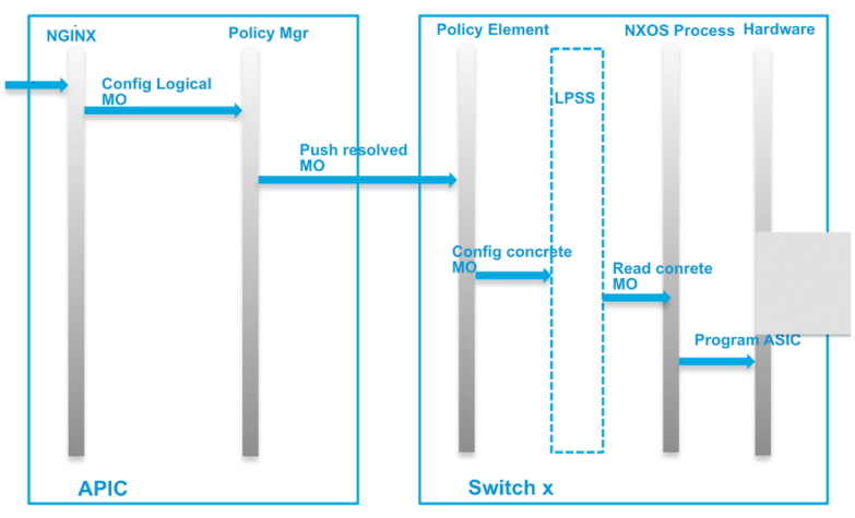
The switches store policy in a place called LPSS (local persistent something something). LPSS is actually a step in programming before hardware and the NXOS process (for example) takes the concrete or resolved objects and programs hardware.

Screen Shot 2015-09-09 at 12.11.52 PM

Here is the test I ran

I decided just to unplug the fabric ports from the VIC on all 3 APICs. Once unplugged these are the steps I took. I also had a ping running from one VM on one host/leaf to another VM on a second host/leaf.
  • Hard power cycle the leafs ( unplug power, reconnect power)
  • Console into a leaf to watch it boot
  • Leaf came back with a name and configuration
    • Pings were still being dropped, ESXI was reporting that the port was down so I assume the module was powering on/ being tested. Finally CDP information was available
    • The pings changed from “destination host unreachable” to “requested timed out” and finally
    • Pings were successful.
  • Confirmed endpoint learning was functioning and VLANs were programmed as expected
  • Plugged the APICs back in
Test was run on code 1.1(2h). Seems everything works as expected!
Also, all my Domains were immediate/immediate.

Resolution and Deployment Immediacy

Introduction

Many of us probably think we know what Resolution and Deployment Immediacy do under an EPG Domains or static paths. This article will clarify exactly what is meant. I know when i first read it i learned something new. Hope you all do too!

Q. What is Resolution Immediacy? What is Deployment Immediacy

A.

Resolution Immediacy = When is policy from the APIC pushed and programmed onto the leafs object model

  • Pre-Provision = pushes policy to the leaf BEFORE a hypervisor is attached to a DVS
  • Immediate = Pushed as soon as a hypervisor is attached to a DVS. A discovery protocol like CDP and LLDP (or opflex for AVS) is then used to form the adjacency and the fabric path.
  • On-Demand = policy is pushed only when a hypervisor is connected AND a VM is placed in a port-group / EPG

Deployment Immediacy = Deployment Immediacy references when TCAM is actually programmed on the switch

  • Immediate = programmed as soon as policy is downloaded onto the leaf
  • On-Demand = programmed as soon as first data plane packet hits the switch

Transit Routing

Hello

Finally getting the time to write this up. Transit routing is a new feature with the ACI 1.1 code. This allows re-distribution from one L3 Out to another, basically this means OSPF can distribute routes into EIGRP and EIGRP can distribute routes into OSPF through the fabric!

In ACI 1.0 code, the fabric was NOT transit. Thats why OSPF had to be a stub area.

Anywho, without getting into too much detail. Lets configure it!

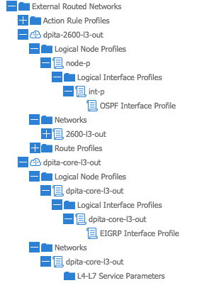
Screen Shot 2015-08-24 at 8.49.43 AM


As you will probably come to notice from following my blog, i always start any configuration with Access Policies. So make sure the access policies, VLAN pools, L3 Domain and AAEP are all configured properly

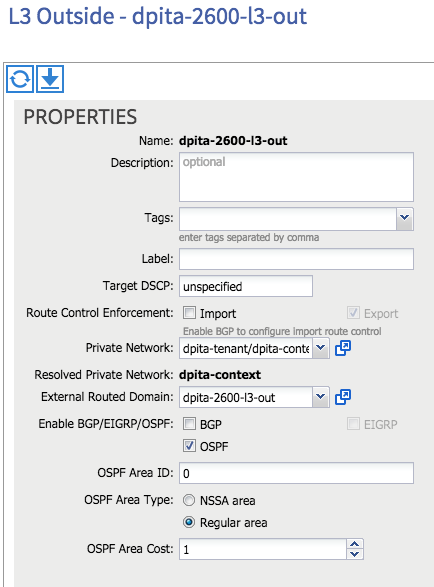
Now, under the tenant, lets create our first L3 out, in this case lets say its OSPF Regular area 0

Screen Shot 2015-08-24 at 9.36.49 AM

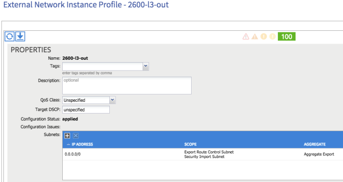
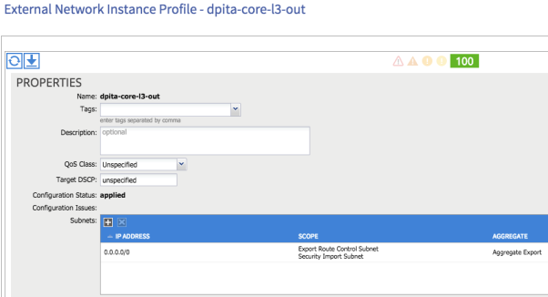
on node 102 with a router ID of 18.18.88.88 with a routed interface of 1/95 and an IP of 1818.18.2/30. Now our L3 EPG (external network instance profile) i my case, i am specifying all subnets with 0.0.0.0/0 and i want to make sure i check:

  • Security import subnet
  • Export Route Control
  • Aggregate Export

Screen Shot 2015-08-24 at 9.37.14 AM

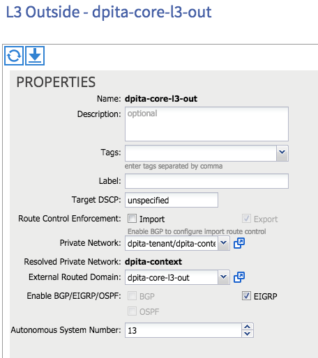
Lets create the second L3 out, which in this case is EIGRP AS 13

Screen Shot 2015-08-24 at 9.36.56 AM

on node 101 with a router ID of 1.4.1.4. the device is on port 1/3 routed interface with an ip of 172.16.4.1/30. It is important to notice the EIGRP Interface Profile dropdown and create an Interface Policy. Overlooking this object will prevent the EIGRP process from starting on the leaf but will program the interface with an IP. Finally, create the L3 EPG with the same settings for the subnet as above

  • Security Import subnet
  • Export Route Control
  •  Aggregate Export

Screen Shot 2015-08-24 at 9.37.25 AM

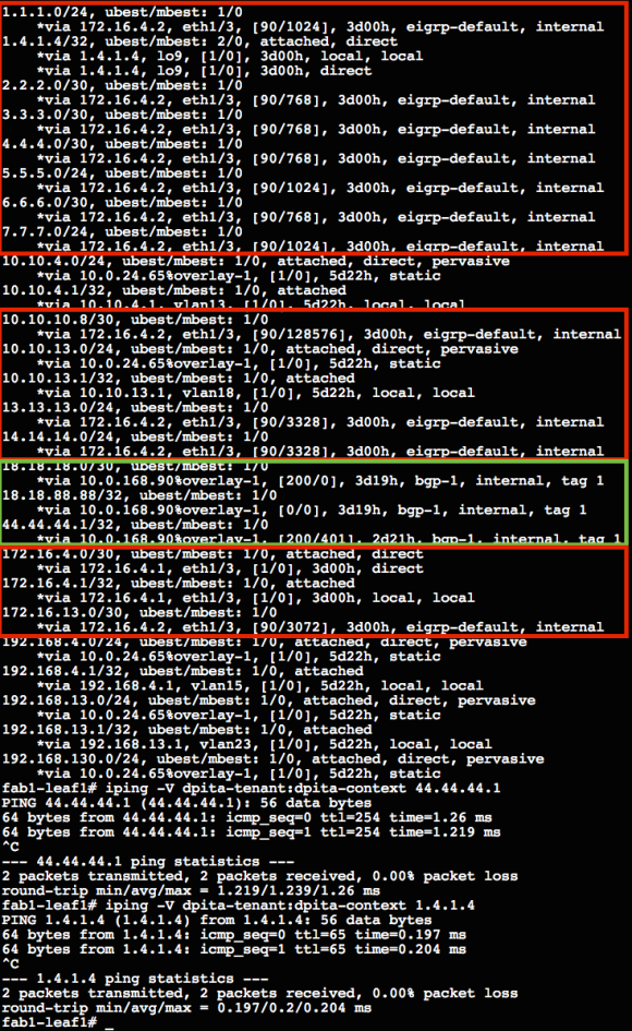
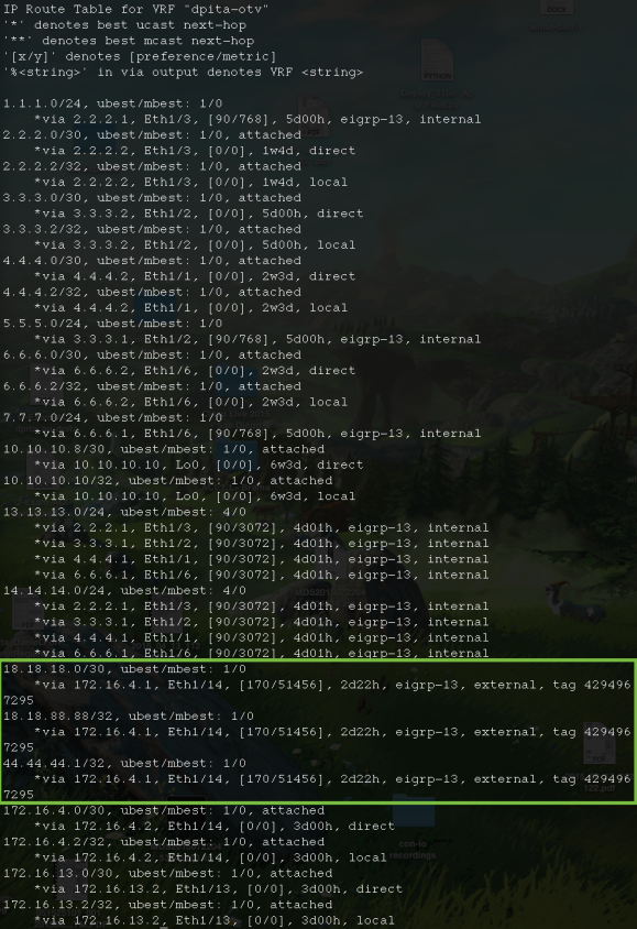
At this point, the ACI routing table should include routes from both the OSPF and the EIGRP side. Both sides should have learned the opposite routes as well.

Here we see the leaf routing table for my VRF. in red is everything learned from EIGRP and in green is what is learned from OSPF.

Screen Shot 2015-08-24 at 9.41.23 AM

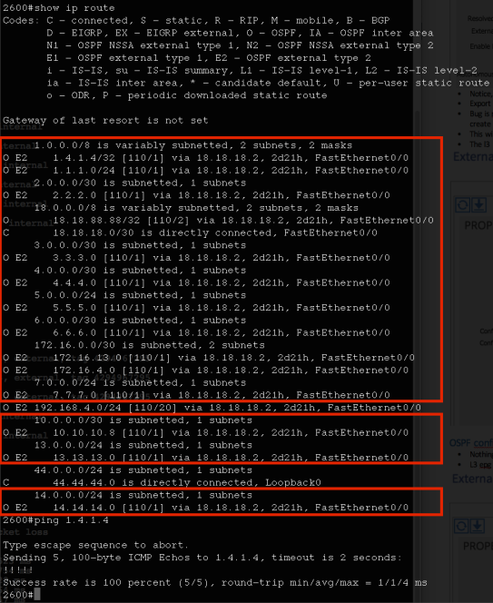
Output from the 2600 running OSPF, all the stuff in red are EIGRP routes redistributed out from the fabric

Screen Shot 2015-08-24 at 9.39.47 AM

And finally, here is the EIGRP router learning OSPF routes in green from the fabric.

Screen Shot 2015-08-24 at 9.51.43 AM

In the case that a BD is to be attached, nothing changes! Mark the subnet as Public and add both L3 outs as a “Associated L3 Out”